


Published on Nov 30, 2023
Couplers, also known as "isolators" because they electrically isolate as well as transmit data, are widely used in industrial and factory networks, instruments, and telecommunications. Every one knows the problems with optocouplers. They take up a lot of space, are slow, optocouplers age and their temperature range is quite limited. For years, optical couplers were the only option.
Over the years, most of the components used to build instrumentation circuits have become ever smaller. Optocoupler technology, however, hasn't kept up. Existing coupler technologies look like dinosaurs on modern circuit boards.
Magnetic couplers are analogous to optocouplers in a number of ways. Design engineers, especially in instrumentation technology, will welcome a galvanically-isolated data coupler with integrated signal conversion in a single IC. My report will give a detailed study about 'ISOLOOP MAGNETIC COUPLERS'.
When equipment using different power supplies is tied together (with a common ground connection) there is a potential for ground loop currents to exist. This is an induced current in the common ground line as a result of a difference in ground potentials at each piece of equipment. Normally all grounds are not in the same potential.
Widespread electrical and communications networks often have nodes with different ground domains. The potential difference between these grounds can be AC or DC, and can contain various noise components. Grounds connected by cable shielding or logic line ground can create a ground loop-unwanted current flow in the cable. Ground-loop currents can degrade data signals, produce excessive EMI, damage components, and, if the current is large enough, present a shock hazard.
Galvanic isolation between circuits or nodes in different ground domains eliminates these problems, seamlessly passing signal information while isolating ground potential differences and common-mode transients. Adding isolation components to a circuit or network is considered good design practice and is often mandated by industry standards. Isolation is frequently used in modems, LAN and industrial network interfaces (e.g., network hubs, routers, and switches), telephones, printers, fax machines, and switched-mode power supplies.
Magnetic couplers are analogous to optocouplers in a number of ways. Optocouplers transmit signals by means of light through a bulk dielectric that provides galvanic isolation
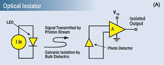
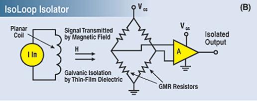
Figure 1. Both optical (A) and magnetic isolators (B) provide galvanic isolation between electronic input and output. Magnetic isolators transmit the signal by a magnetic field rather than by photons.
Magnetic couplers transmit signals via a magnetic field, rather than a photon transmission, across a thin film dielectric that provides the galvanic isolation. As is true of optocouplers, magnetic couplers are unidirectional and operate down to DC. But in contrast to optocouplers, magnetic couplers offer the high-frequency performance of an isolation transformer, covering nearly the entire combined bandwidth of the two conventional isolation technologies.
Large magnetic field dependent changes in resistance are possible in thin film ferromagnet/nonmagnetic metallic multilayers. The phenomenon was first observed in France in 1988, when changes in resistance with magnetic field of up to 70% were seen. Compared to the small percent change in resistance observed in anisotropic magnetoresistance, this phenomenon was truly ‘giant’ magnetoresistance.
The spin of electrons in a magnet is aligned to produce a magnetic moment. Magnetic layers with opposing spins (magnetic moments) impede the progress of the electrons (higher scattering) through a sandwiched conductive layer. This arrangement causes the conductor to have a higher resistance to current flow.
An external magnetic field can realign all of the layers into a single magnetic moment. When this happens, electron flow will be less effected (lower scattering) by the uniform spins of the adjacent ferromagnetic layers. This causes the conduction layer to have a lower resistance to current flow. Note that these phenomenon takes places only when the conduction layer is thin enough (less than 5 nm) for the ferromagnetic layer’s electron spins to affect the conductive layer’s electron’s path.
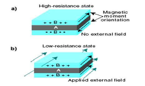
Figure 2—In both a and b, the A layers are the nonmagnetic conductive layer and the B layers are adjacent magnetic layers of opposing orientation. a—Layer A is high resistance because of higher scattering of electrons flowing through it. b—An applied magnetic field realigns the magnetic moments in the B layers, resulting in a lower resistance in lay
The resistance of two thin ferromagnetic layers separated by a thin nonmagnetic conducting layer can be altered by changing the moments of the ferromagnetic layers from parallel to antiparallel, or parallel but in the opposite direction.
Layers with parallel magnetic moments will have less scattering at the interfaces, longer mean free paths, and lower resistance. Layers with antiparallel magnetic moments will have more scattering at the interfaces, shorter mean free paths, and higher resistance
| Are you interested in this topic.Then mail to us immediately to get the full report.
email :- contactv2@gmail.com |
